=============== Control Utility 3: ================
............... GPS Route Control .................
A method needs to be developed by which a drone can find its target autonomously. How this can be achieved will be discussed in the following.
It is assumed that the earth is a sphere with a radius R_Earth = 6371000 m. To describe a position at this 3-D surface GPS makes use of a spherical coordinate system. In this system the position is described in terms of degrees Long(itude), degrees Lat(titude) and earth radius. Lon and Lat coordinates of the Target T need to be set by the user, and these values can for example be found in Google Maps. The user has to store these values in degrees in file
"9_Targets_Lon_Lat.ino"
Based on the specs of the drone, the max.flight distance is set by the user in the relevant global variable section. This value is used for control purposes before take-off.
On a regular basis a limited number of GPS data are read by function
"13_Get_GPS_Data.ino"
This set of data is then analysed by function
"14_Process_GPS_Data.ino"
In case the analysis of the GPS data-set is successfully the Lon and Lat values of Actual position A of the drone is found. This position is regulary updated over time.
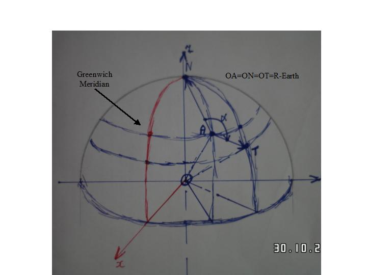
With the Geographical North-Pole N (Spherical Coordinates Lon=0 deg, Lat=0 deg.) as third point, two vectors AN and AT are constructed. The angle ALPHA is enclosed by these two vectors as shown in below Figure. Relative to Geographical North this angle ALPHA defines the direction from actual point A to target T.

Sec3-Control3-Fig.1: Target-Heading.
The sperical coordinate system is not suitable for further development of the angle control method. A right handed carthesian x,y,z coordinate system is constructed with its origin in the earth center. The x and y-axis laying in the equatorial plane. The z-axis is vertical to the x-y plane. The orientation of the x,y,z system is such that the Greenwich prime meridian lies in the x-z plane. The y-axis points East. The Geographical North-Pole N lies on the z-axis and the coordinate values x=0, y=0 and z= R_Earth.
After converting the spherical GPS coordinates from degrees to radians, the cartesian coordinates x,y,z of the actual point A are calculated as follows:
x_A = R_Earth * cos(Lat_rad_A) * cos(Lon_rad_A) [m]
y_A = R_Earth * cos(Lat_rad_A) * sin(Lon_rad_A) [m]
z_A = R_Earth * sin(Lat_rad_A) [m]
Similar to above the carthesian coordinates x_T, y_T and z_T of Target point T are calculated. These coordinate transformations is done by calling function
"15_Heading_Calcul.ino"
Now the vectors AN and AT are known in the carthesian system the angle ALPHA is calculated with the scalar vector product.
During the flight, the flight-control function has to keep the drones nose-tail line pointing direction target. The YAW-angle GyroYaw of the nose-tail line is defined relative to Geographic North. This angle is delivered by the 12_function
"12_Calc_Pitch_Roll_Yaw.ino"
The angle DeltaYaw, and the smallest rotation CW or CCW to point the Drone's nose towards the Target T is deliverd by caling function.
"16_Heading_Rot_Angle_cw_or_ccw.ino"
Finally angle DeltaYaw and the relevant Rotation (Sign) are used by the
"20_PID_Yaw_Controller.ino"
to keep the Drone facing direction Target.
Simultaneously heading progress is checked with the distance calculation from actual point A to target point T.
It is clear from above, for succesfull hitting the target well calibrated Sensors is essential. Calibration of sensors is discussed in Section 2: Calibration Utilities.
Free-Drones Company 2022