================== Utility 1: ===============
................ The Test Bench .............
On behalf of the flight control software development, utilities development, sensor calibration and testing, software testing in general etc., a stand-alone testbench is built. A picture of the Test-Bench is shown in below Figure.

Test-Bench-Fig.1: Teensy 4.0 based Test-Bench Module.

The module comprises the following components:
- A Teensy 4.0 micro-processor. This is the heart of the system. The Teensy is plugged in a Standard Terminal Adapter Board normally used for the Arduino Nano, and is connected with its micro-USB port to a Windows Lap-Top/PC.

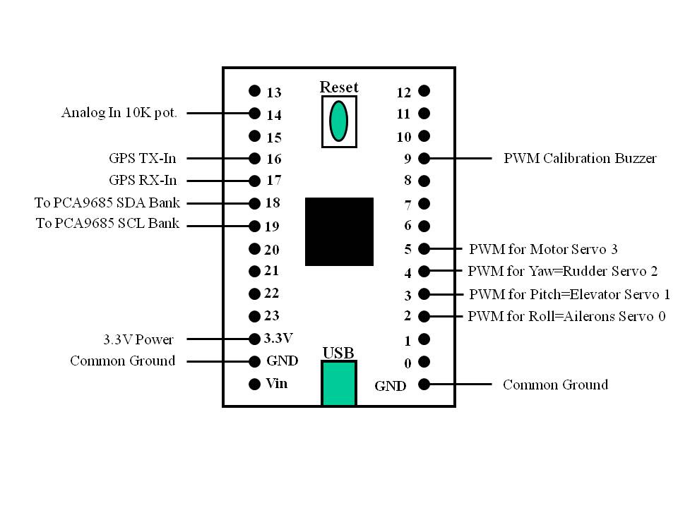
Test-Bench-Fig.2: Teensy 4.0 Test-Bench Module and Drone Connections.
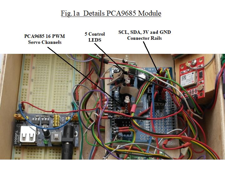
- A PCA9685 16 channel PWM servo driver shield. This shield is planned to be used to control servo's needed for Payload delivery and LED's to visiualize status info of the system. The prototype area of the board is used for soldering common pin-onnector banks. A bank for Ground, a bank for +3.3V power, a bank for SCL and bank for SDA connections. The SCL bank is connected to Teensy's pin 19 i.e. SCL0 and the SDA bank is connected to Teensy's pin 18 i.e. SDA0.
- A 3.3V-5V power module. 5V is used for (external) powering the flight-control servo's.
- An add-on to the Test Module is a 5cm wooden cube as shown in below picture. Sensors are attached to this cube and connected to the bench with 3.3V power and I2C connections.
a

Test-Bench-Fig.3: 5x5x5cm Wooden Cube used for sensor calibration.
The GY-521 MPU-6050 combined accelerometer and gyro shield, and the HW351 MAG3110 magnetometer shield are clamped to the wooden cube.
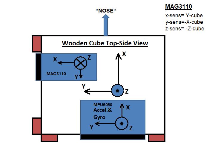
Note: As shown in below Fig.4, the x-,y-,z-axis orientation of the HW351 MAG3110 magnetometer is NOT a right-handed coordinate system!!
Both sensors are wired to the relevant connector banks of the PCA9685 board. Calibration of these attitude and orientation sensors is discussed in Section 2 of this Web-Site. The picture below shows the orienation of the sensor axis in relation to the axis frame as defined for the wooden cube, and drone.

Util1-Fig.4: Sensor Orientation of Wooden Cube.
- For take-off and altitude during the a barometric sensor is used. The BMP280 AirPressure Sensor is connected to the relevant I2C, power and ground connector banks of the PCA9685 board. Details of the altitude control system is discussed in Section 3 of this Web-Site.
- The NEO6MV2 GPS-board is directly connected to the Teensy. The 3.3V power and Ground are wired to the relevant banks on the PCA9685 board, but the RX-pin of the GPS board is connected to TX4-pin (pin 17) of the Teensy, the TX-pin of the GPS board is wired the to RX4-pin (pin 16) of the Teensy. The GPS system is discussed in Section 2 of this Web-Site.
- An auxilliary 10K Lin.Potentiometer. This Pot-meter is used for motor testing and testing the implementation of the manual emergency motor-control option. For this the middle-pin of the potentiometer is connected to the Teensy's A0-pin 14: analog input. The outer pins are either connected to 3.3V or Ground. Details of this system is discussed in more detail in Section-3 on Emergency Motor Control.
- A Buzzer is connected to PWM pin-9. The signal of this little device is used during the data aquisition phase of the calibration process of the HW351 MAG3110 magnetometer. This is discussed in Utility 2 of this Section-1.
- Finally Teensy' PWM pins 2, 3, 4 and 5 are used for controling the 4 flight-control servo's.
Free-Drones Company 2022